PF Softstarter Open Gate Phase Faults F7, F8 & F9
Problem:
What will cause an F7 Open Gate Phase A, F8 Open Gate Phase B, F9 Open Gate Phase C errors or faults on a PF controller? How can I troubleshoot these faults?
Cause:
The PF controller measures both back EMF and current via built in CTs. The PF controller uses both measurements to determine if the SCR's are conducting. This method has the advantage of working well on very high efficiency motors where voltage is not a sufficient means of monitoring the SCR. It has a disadvantage when undersized motors are used. An Open Gate fault is only generated while the PF soft starter is starting or stopping the motor (never before firing the SCRs and never while at speed).
Open gate faults indicate that an abnormal condition has caused faulty firing of the SCRs (e.g., open SCR gate) during the start sequence. The PF controller will attempt to start the motor a total of three times before the controller shuts down on these faults.
Possible Causes Of These Faults Include:
- The controller has determined that the SCRs are not conducting properly or that they are not conducting at all. The control module detects repeated instances where one SCR in the power pole is firing while the other is not firing. This will cause an open gate fault to be generated. Typically it takes 50-60mS to determine that an open gate condition exists.
- Loose gate lead connections or wires located on the PF control module.
- The motor is lightly loaded. Because the firing of the SCRs is determined by monitoring current, an Open Gate fault may occur if the Motor's FLA falls below the minimum FLA range of the PF softstarter. This would ONLY happen during starting or stopping, not running.
- The PF's current sensing circuit (CT) is designed to work for a given current range. If the motor running current does not fall within the PF’s motor current range then the SCR conduction cannot be sensed by the controller.
- Incoming Noise or Voltage spikes on the 3 phase power supply to the line side of the PF controller. Noise can be produced from Variable Frequency Drives (VFD)s or welding equipment.
- Components on the PF control module are damaged.
Solution: Follow The Steps Below:
- Remove the control module from the PF controller. Check gate lead connections to the control module. Verify the connections are tight.
- Perform Line to Load Resistance Checks on each power pole with the motor disconnected and all power removed. If the resistance readings are less than 10,000 ohms, replace the power pole.
- Verify Noise conditions via an Oscilloscope or other measuring equipment. If noise conditions exist, the following programming changes can be made. These parameters can be found in the Linear List menu.
- Configure the Line Fault Parameter 84 to Disable F41. The default setting of this parameter is Enable.
OR - Configure the I Shut Off Level Parameter 113 to 20. The default setting of this parameter is 0. And configure the V Shut Off Level Parameter 117 to 0. The default setting of this parameter is 25.
- Determine if the PF control module is causing this issue by doing the following steps.
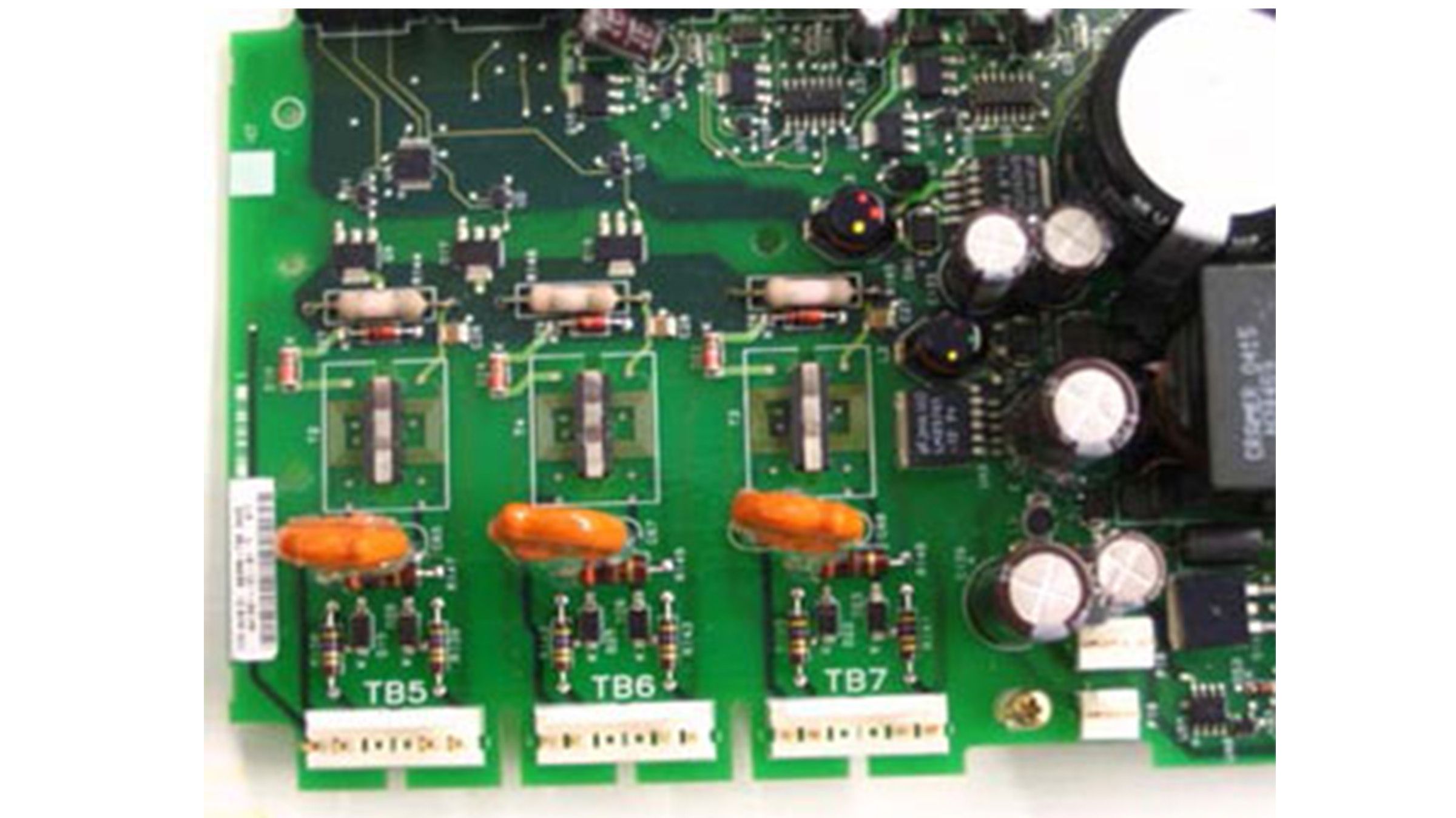
The following steps are for Fault F7 Open Gate Phase A- Set the multi-meter to Diode Check
- Check the SCR gate of SCR 1 and 2 on Phase A. The circuit board silk screen will indicate the pin number.
- DMM Positive (+) on TB5 Pin 6 and DMM Negative (-) on TB5 Pin 5 should measure approximately 0.5 volts. If the multi-meter leads are reversed then the meter will measure open ohms.
- DMM Positive (+) on TB2 Pin 2 and DMM Negative (-) on TB5 Pin 1 should measure approximately 0.5 volts. If the multi-meter leads are reversed then the meter will measure open ohms.
- Repeat the above steps for TB6 (F8 Open Gate B) and TB7 (F9 Open Gate C) with same pin numbers used with TB5.

Replace the Control Module if these measurements shown above are exceeded.
For additional information please contact your nearest authorized distributor, sales representative, or call our customer service or technical support lines.
